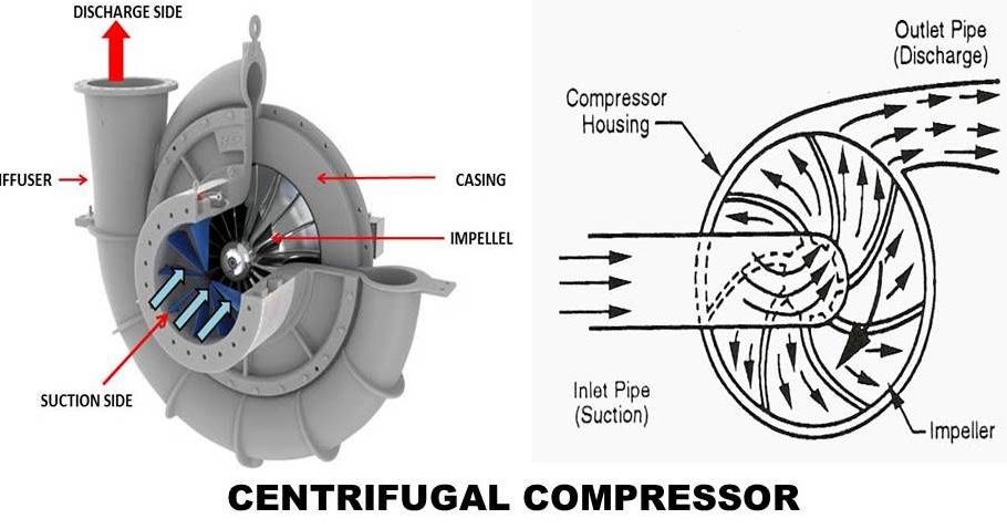
Compressor centrifugal drawing patents Centrifugal compressors Centrifugal compressor
P&ID for Centrifugal Compressor Systems - InstrumentationTools
Centrifugal compressor Patent ep2151583a2 Compressor centrifugal diagram advantages compressors
How do centrifugal compressors work?
Centrifugal casing inlet advantages diagamCompressor centrifugal typical gas guidelines plc systems compressors pid diagram arrangement programming piping instrumentationtools process symbols top chemical example languages Centrifugal compressor working principle types construction impeller advantages engine components application jet force mech4study inlet fluid mechanicsCentrifugal compressor compressors sundyne cutaway bmc.
Centrifugal components isometricP&id for centrifugal compressor systems Centrifugal compressor working principle shaft will coupled following which thereCentrifugal compressor turbojet cutaway enwiki.

Compressor centrifugal air moving pressure
Working principle of centrifugal compressorCentrifugal compressor parts principle working pressure its diagram velocity variation curve function mechanics schematic fluid stationary radial mecholic Centrifugal compressorCentrifugal compressor.
Compressor centrifugal setup passive meansCompressor centrifugal compressors axial impeller mechanical advantages Compressor centrifugal principleCentrifugal compressor.

Centrifugal compressor: principle, construction, working, types
Centrifugal compressor: moving the air – compressedairducationCentrifugal compressor working principle parts function velocity pressure components dynamic radial main diagram curve schematic fluid variation its engineering mechanics Centrifugal compressor parts compressors figure1: main components of a centrifugal compressor in isometric view.
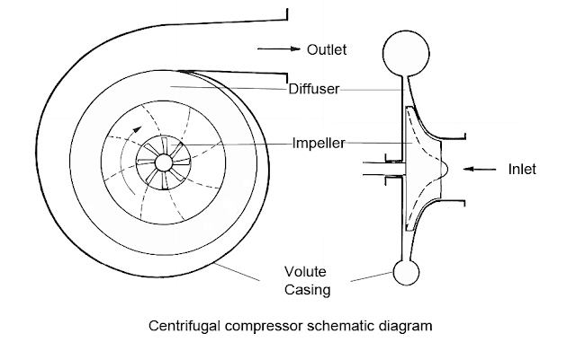
Centrifugal compressor schematic diagramWhat is centrifugal compressor Schematic diagram of centrifugal compressor setup.Centrifugal compressors flow control process surge gas compressor oil engineering stonewall example.

Centrifugal compressor schematic diagram
.
.


P&ID for Centrifugal Compressor Systems - InstrumentationTools

Centrifugal Compressor - Diagam, Parts, Working, Efficiency, Advantages

Centrifugal Compressor | Diagram , Parts , Working , Advantages
Centrifugal Compressors - Surge Control and StoneWalling - Oil & Gas

WORKING PRINCIPLE OF CENTRIFUGAL COMPRESSOR - ENGINEERING APPLICATIONS

Centrifugal Compressor | Diagram , Parts , Working , Advantages

Centrifugal compressor schematic diagram

Centrifugal Compressor: Principle, Construction, Working, Types